


-
INDUSTRIES
-

Precast Concrete Plant
-

Steel Industry
-
Paper Industry
-
Waste to Energy and Biomass Industry
-
Power Industry
-

Overhead Cranes for Automotive Production: Smart Solutions for Enhanced Efficiency
-
Port Machines Industry
-

Manufacturing Industry
-
Different Types of Container Cranes, Shipyard Cranes, Cargo Cranes Used in Port, Harbor and Quay
-

Overhead Cranes for Timber Lifting: Efficient and Safe Wood Handling
-
Overhead Cranes for the Aviation Industry: Streamlining Aircraft Assembly, Maintenance, and Repair
-

Overhead Cranes for Food and Beverages: Ideal for improving productivity and food safety
-
Overhead Cranes for Aerospace Industry: Key Role in Efficient Rocket Manufacturing and Launch
-
-
EQUIPMENT
-
Overhead Cranes
-
Single Girder Overhead Crane
-
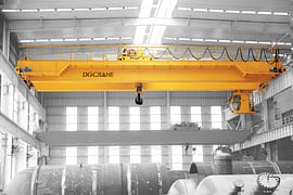
Double Girder Overhead Crane
-
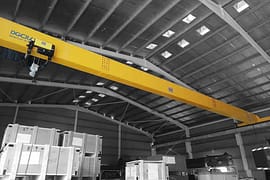
FEM Standard Overhead Cranes
-
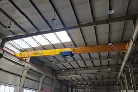
Low Headroom Overhead Cranes
-
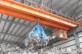
Grab Bucket Overhead Crane
-
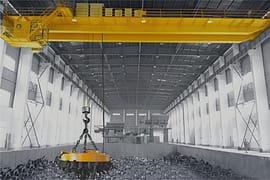
Electromagnetic Overhead Cranes with Lifting Magnet
-
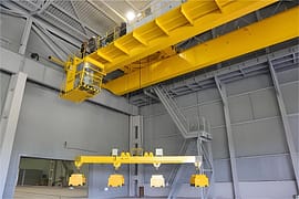
Electromagnetic Overhead Cranes with Magnet Beam
-
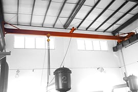
Manual Overhead Cranes
-
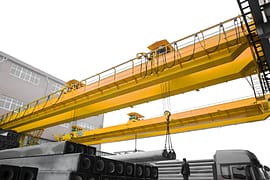
Double Trolley Overhead Cranes
-
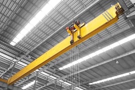
LDP Single Girder Overhead Cranes
-
- Eot Cranes
- Gantry Cranes
- Jib Cranes
-
Hoist & Winch Trolley
-
Electric Wire Rope Hoists
-
FEM Standard Wire Rope Electric Hoists
-
FEM Standard Electric Chain Hoists
-
Crane Trolley
-
Chain Hoists
-
Electric Winch
-
Manual Chain Hoists
-
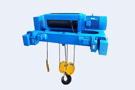
Double Girder Trolley Electric Hoists
-
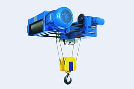
Low Headroom Wire Rope Electric Hoist
-
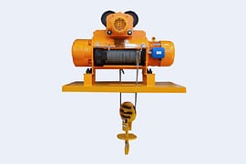
Electric Hoist for Molten Metal
-
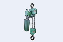
Pneumatic (Air) Chain Hoists
-
Lever Hoists
-
Electric Hoists
-
- Workstation Cranes
- Portable Gantry Cranes
- Explosion Proof Cranes & Hoists
- Special Cranes
- Port Cranes
- Electric Transfer Carts
-
Overhead Cranes
-
CRANE PARTS
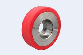
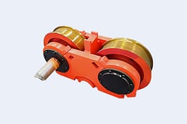
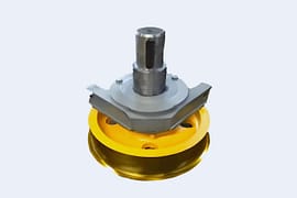
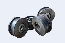
- Crane Wheel Assembly
- Crane Grab Buckets
- Crane Tongs
- Crane Spreader
- Crane Drives
-
Crane Electrical Equipment
-
Overload Limiter
-
Crane Cabin
-
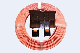
Crane Power Supply System
-

Explosion Proof Crane Radio Remote Controls
-

Joystick Type Crane Radio Remote Controls
-

Pushbutton Type Crane Wireless Remote Controls
-
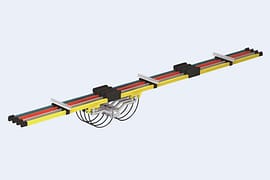
Single-pole Insulated Conductor Rails
-
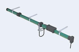
Enclosed Conductor Rails
-
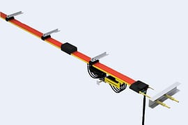
Seamless Conductor Rails
-
Copperhead Conductor Rails
-
Overhead Crane Cables
-
- Other Cranes Parts
- ABOUT US
- CONTACT US
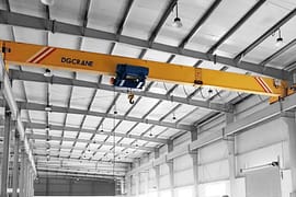
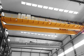



Single-girder Overhead Cranes Exported to Brazil for Injection Molding Workshop
Table of Contents
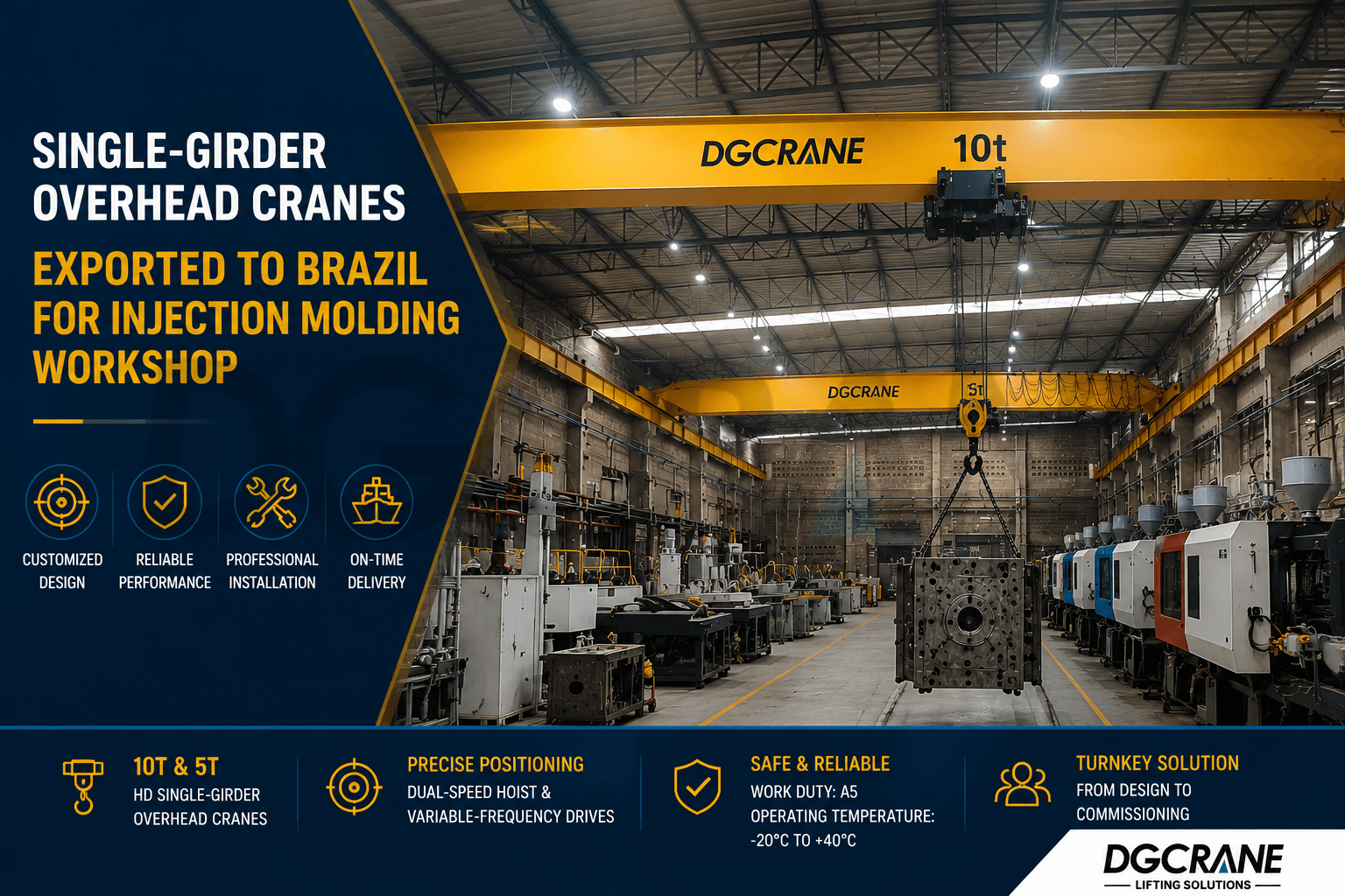
A Brazilian injection molding plant urgently needed two electric single-girder overhead cranes to handle heavy mold changes and the inter-station transfer of raw materials and finished products within the workshop. However, the person in charge was a complete novice regarding lifting equipment—unfamiliar with how to measure the span, which crane was best suited to the facility, or which supplier could provide end-to-end service. Although DGCRANE had no local office in Brazil, we were ready to travel there. From dispatching a technical engineer to Brazil for a site survey and finalizing the design, through to completing production and shipping within 30 days, and finally sending an engineer back to oversee installation and commissioning, DGCRANE successfully delivered two custom HD single-girder overhead cranes that are now fully operational in the injection molding workshop.
Project Background
The client, a Brazilian injection-molded products manufacturer with multiple parallel production lines, faced challenges after capacity expansion: higher mold change frequency and heavier components led to low operational efficiency and safety risks in heavy mold handling. Furthermore, lacking crane specification expertise and in-house installation personnel, they needed a practical turnkey solution.
We therefore decided to dispatch an engineer directly to Brazil to inspect the client’s production facility. After a journey of over 30 hours, the engineer proceeded straight from arrival to the factory floor to conduct a comprehensive survey, measuring parameters such as span, clear height, rail elevation, column locations, and the distribution of obstacles.
Core Challenges We Have Met
Workshop 1: Inclined Intermediate Columns & No Corner Corbels
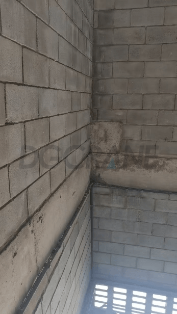
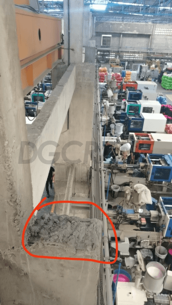
The engineers first inspected the condition of the corbels on the workshop columns. The corbels measured 300mm in width and 420mm in length, but their surface conditions were inconsistent: on the left side of the workshop, the embedded steel plates protruded by 400mm, whereas on the right side, they extended 410mm but were covered by 2–3cm of residual concrete, effectively reducing the usable surface area. A more critical issue was the absence of embedded steel plates on the corbels themselves and of embedded components along the sides of the columns, which meant the crane runway beams could not be mounted directly onto the existing structure.
Subsequent elevation measurements revealed even more serious problems: the columns in the middle of the workshop leaned inward, with side measurements indicating reduced clearance in the center. This implied that if the design used standard end spans, the crane would collide with the columns at the middle section. Furthermore, no corbel brackets were installed at the workshop’s four corners. Consequently, to extend the crane’s operating range, welded steel frames would need to be added at these locations.
Additionally, the workshop featured a solid wall on one side and exposed columns on the other—an asymmetrical layout requiring different mounting methods for the crane runway beams: chemical anchors would be used to secure beams to the wall. In contrast, connections to the column side would require prior preparation of embedded plates.
Workshop 2: Misaligned Corbels & Missing Corner Corbels
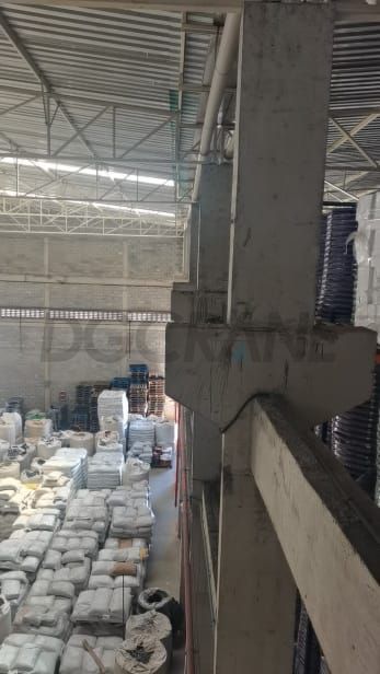
Upon entering the second workshop, the engineer encountered a similarly challenging situation. The corbels in the four corners lacked proper finishing, and the concrete surfaces were uneven, with exposed rebar ends. Before the crane runway beams could be installed, the excess concrete had to be chipped away, and the surfaces ground level; otherwise, the runway beams would sit askew. Furthermore, none of the corbels featured embedded steel plates, nor were there any embedded components on the sides of the columns—deficiencies that required rectification before installation.
While measuring the height difference between the left and right corbels, the engineer identified a critical issue: the left corbel was approximately 6.707 meters above the floor, while the right was about 6.753 meters—a discrepancy of nearly 5 centimeters. However, successful installation required the top surfaces of the corbels to be perfectly level; otherwise, the rails would be sloped, causing the crane to drift during operation. The engineer documented the elevation of each corbel, noting the specific locations requiring adjustment and the magnitude of the deviations, so the client could complete the necessary civil engineering corrections before the equipment arrived.
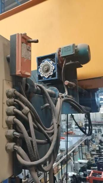
Our engineers also noted an existing crane with a combined main/trolley travel control box, unlike our standard separate units. This detail was recorded for the new crane's independent electrical system design. Low-noise motors were selected for the new crane to meet environmental requirements.
Survey-to-Solution: Custom One-on-One Crane Design
After compiling the survey data, our structural and electrical engineers began designing specific solutions for each issue identified on-site. The design of these two overhead cranes—covering everything from main girder cross-sections and wheel load distribution to the positioning of limit switches—was tailored specifically to the actual operating conditions measured.
Workshop 1: 10T HD Single-girder Overhead Crane
Due to the inclined columns, the mid-span usable width is narrower than at the ends, so the main girder cannot be sized by the end-measured standard span. Based on workshop dimensions, engineers calculated custom runway beam specs with unequal total lengths for both sides:
- Side 1: 4.58m + (5m × 10 segments) + 4.76m
- Side 2: 4.9m + (5m × 10 segments) + 4.68m
Furthermore, a conventional LD single-girder crane design would result in higher dead weight and greater wheel pressure, exceeding the load-bearing capacity of the existing factory’s concrete corbels. Therefore, based on finite element analysis, we selected the HD single-girder crane model. For the same specifications—and while maintaining the same L/800 stiffness standard—this model allows for a 22% reduction in main girder section height and a decrease in maximum wheel pressure of approximately 5% compared to conventional designs.
Based on the solutions outlined above, the finalized crane drawings and specifications are as follows:
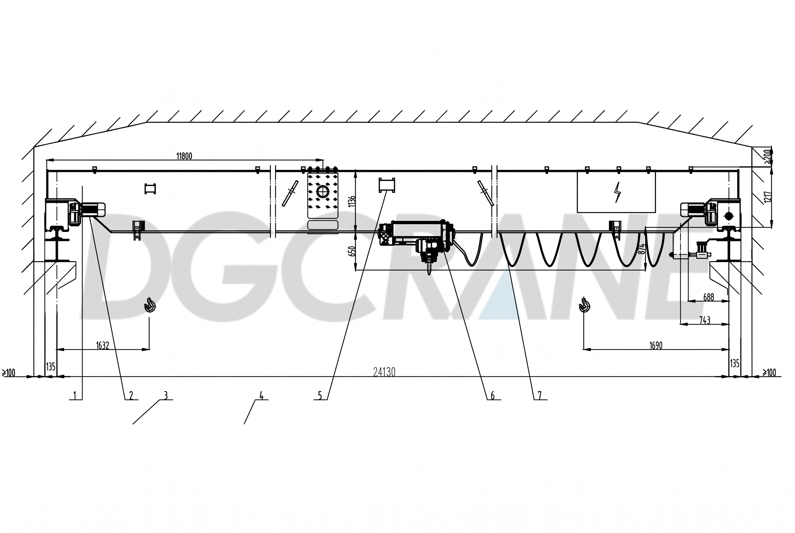
- Capacity: 10T
- Span: 24.13m
- Lifting Height: 9.81m
- Lifting speed: 0.8/5.0 m/min (double speed)
- Hoist travelling speed: 2-20 m/min (variable-frequency speed control)
- Work Duty: A5
- Voltage: AC 380V 50Hz
- Dual-mode operation: wireless remote control and wired handheld controller
- Operating temperature: -20°C to +40°C
- Shipped together with the matching crane runway beams
Workshop 2: 5T HD Single-girder Overhead Crane
The existing workshop structure strictly constrained the rail placement, leaving no room for span adjustment and requiring millimeter-level precision. Consequently, engineers determined the positioning for each end of the main girder based on the actual measured coordinates of the supporting corbels; they established specific limit positions for both ends to ensure the crane would operate without colliding with the existing workshop structure.
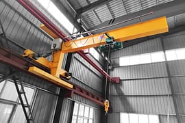
Another factor to consider is the limited vertical clearance in the workshop: the area beneath the roof is already densely packed with lighting fixtures and metal trusses. However, the injection molding workshop requires the lifting and transport of large molds, necessitating a greater lifting height. A conventional LD single-girder crane utilizes an I-beam structure with an underslung hoist trolley, resulting in limited effective lifting space. The HD single-girder overhead crane fits compact spaces better. Its trolley is side-mounted on the box girder, lowering hook height to maximize lifting range and working coverage. Final crane specifications and drawings are shown below:
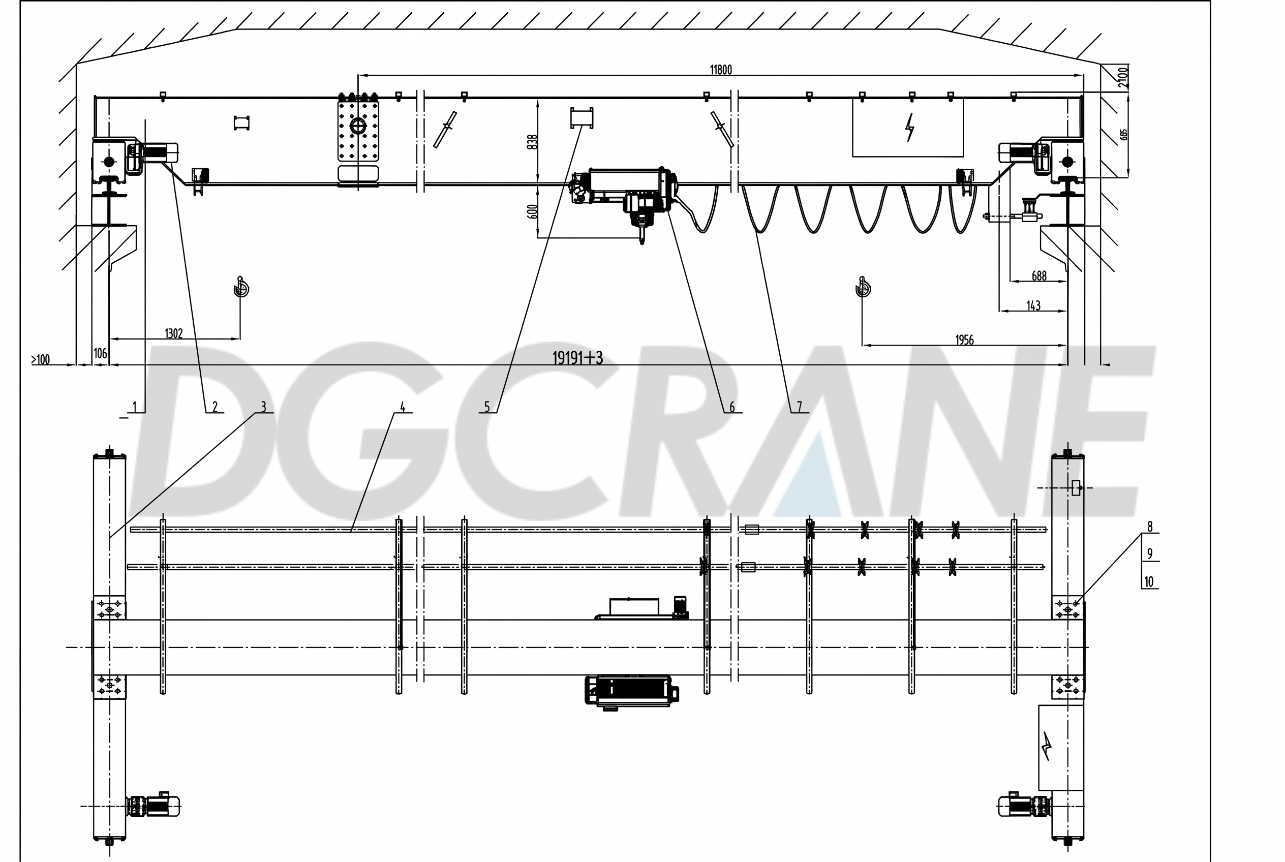
- Capacity: 5T
- Span: 19.191m
- Lifting height: 6.12m
- Lifting speed: 0.8/5.0 m/min (double speed)
- Hoist travelling speed: 2-20 m/min (variable-frequency speed control)
- Crane travelling speed: 3-30 m/min (variable-frequency speed control)
- Work Duty: A5
- Voltage: AC 380V 50Hz
- Dual-mode operation: wireless remote control and wired handheld controller
- Operating temperature: -20°C to +40°C
- Shipped together with the matching crane runway beams
Operational Strategy: Precision Positioning
During the site assessment, we learned that the client's workshop required frequent mold flipping, with the heaviest molds weighing up to 7 tons. The flipping process involves moving the mold from a horizontal to a vertical position and back again; this requires the crane to maintain stable, precise “inching” capabilities at low speeds throughout the operation. Excessive speed causes the mold to sway, while insufficient speed prolongs the overall mold-change cycle. Conventional LD single-girder overhead cranes—which typically feature a single hoisting speed and lack variable frequency drives (VFDs) for the trolley and bridge—rely on operator “inching” and manual feel, making alignment accuracy entirely dependent on experience.
The client was unfamiliar with crane speed control systems—nor did they need to be. Our role was to translate their operational requirements into equipment specifications. We implemented a two-speed hoisting system: a high-speed mode to quickly lift the mold to a safe height, and a low-speed mode (0.8 m/min) for smooth movement during mold alignment and flipping. With a speed ratio of 6.25:1, the system ensures the mold remains stable when switching between speeds. For the bridge drive, we utilized Schneider VFDs to enable automatic high-speed operation when unloaded and automatic speed limiting when fully loaded; this allows operators to simply hold down the remote control without the distraction of manually managing speed settings.
Electrical Control: Efficient & Labor-Saving
As the existing electrical control boxes for the crane (long-travel) and trolley (cross-travel) mechanisms featured an integrated design, the system faced risks such as a high failure rate due to cable dragging, difficult maintenance, and increased overall crane weight. Our Engineers recommended replacing the hoist trolley’s control box and the entire electric hoist unit, configuring them to operate independently of the crane’s electrical system. Heavy-duty aviation-grade connectors were used for all connections, ensuring secure mating and facilitating quick, simple assembly. Additionally, the connection points were protected with insulating plastic sleeves. Inside the control boxes, wiring was routed through protective trunking to ensure circuit safety and extend service life.
On-site Installation & Commissioning: Full On-site Service
As the client did not have an installation team, and in accordance with the contract, we dispatched engineers to Brazil for a second visit—following the equipment’s arrival and customs clearance—to provide on-site supervision throughout the installation and commissioning process. Upon arrival at the factory, the engineers first aligned the installation plan with the client’s project lead, clarifying daily work milestones, the required workforce and tool lists, safety protocols, and acceptance criteria. Work then commenced on the shop floor. We addressed the following issues:
Installation of Crane Runway Beams and Alignment of Rail Reference Surfaces
During the initial survey, the engineers documented the elevations, embedded plate locations, and wall conditions for all corbels across both workshops. Before the equipment’s arrival, the client completed the installation of the embedded plates based on the drawings we provided; any corbels with excessive deviations were either chipped back or leveled via grouting—all of which was finished before the engineers’ second visit.
After placement of crane runway beams, engineers used an optical level to calibrate elevations before installing rails. Millimeter-level accuracy for track spacing posed the biggest challenge. A total station took measurements every 2 meters, with fine adjustments made until all readings complied with standards. For the concrete workshops, crane runway beams were fixed to corbels and laterally anchored to walls with chemical anchor bolts. Engineers supervised drilling, cleaning, grouting and bolt installation, and inspected hole dimensions, cleaning work and curing time throughout the process.
Hoisting and Power-on
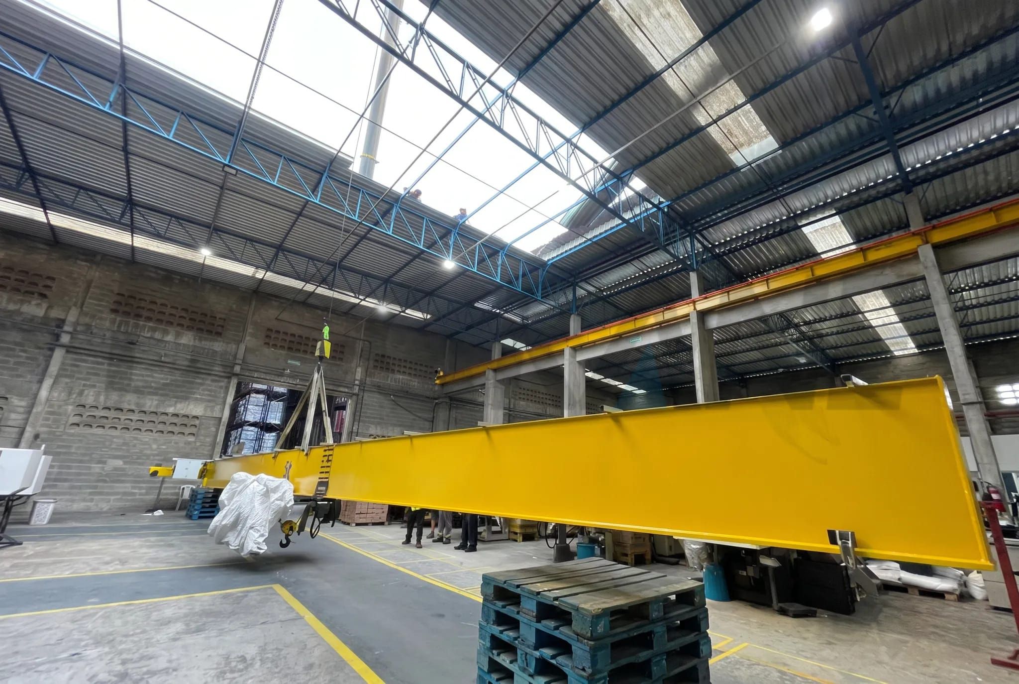
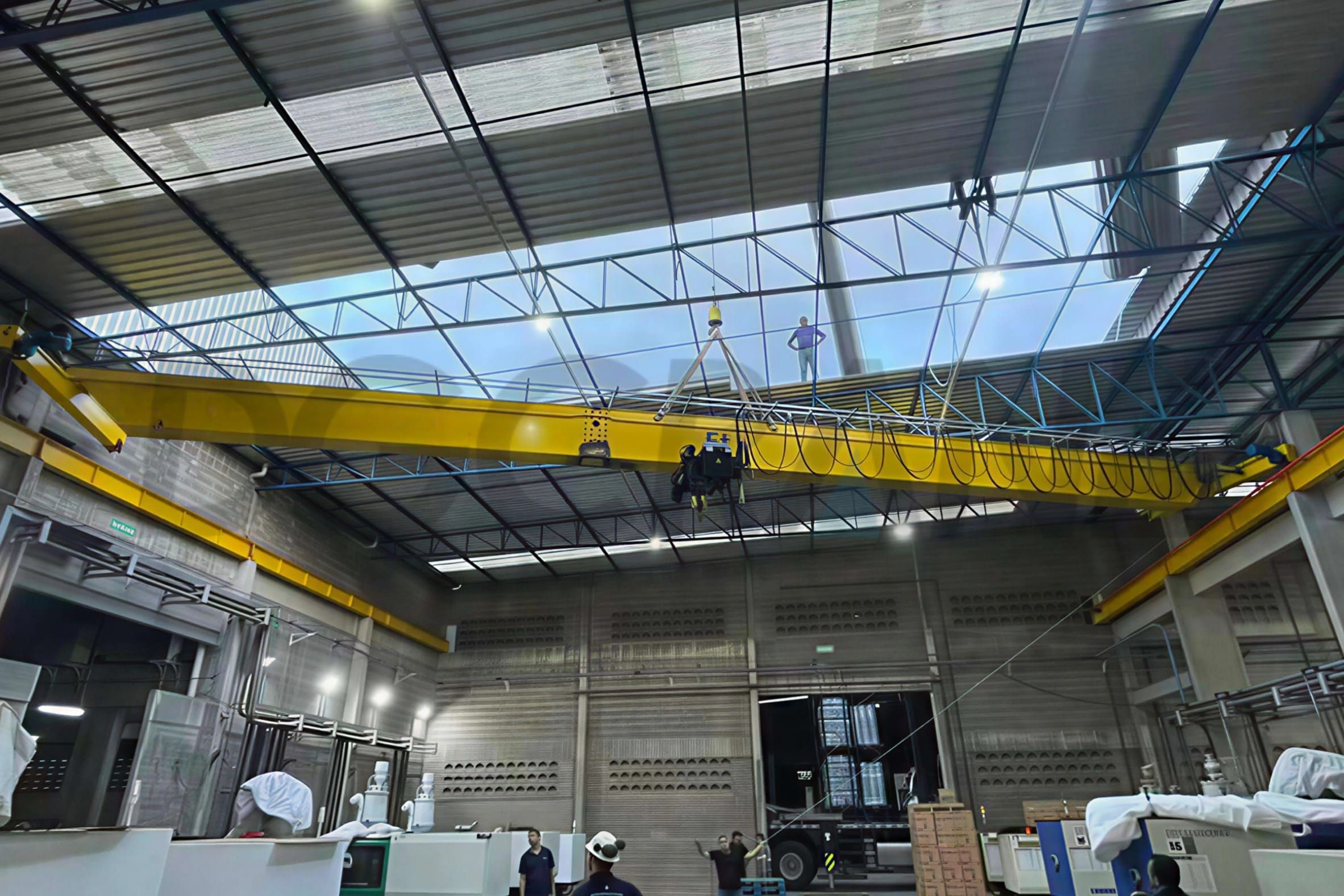
Before the crane is lifted, technical personnel verify the lifting points and mark the center of gravity. The main girder and end beams are assembled on the ground, with positioning bolts securely tightened. Hoist trolleys are mounted on both sides of the main girder flanges, followed by the sequential installation of buffers, limit switches, and special steel brackets. Next, the trailing cables and conductor support frames for the hoist trolleys are installed, along with the crane’s electrical cabinet and current collector brackets. Once all components are installed, a comprehensive inspection of the equipment status is conducted, followed by power-on commissioning. Finally, a truck crane lifts the entire assembly into position on the crane rails.
Load Testing and Static Load Tests
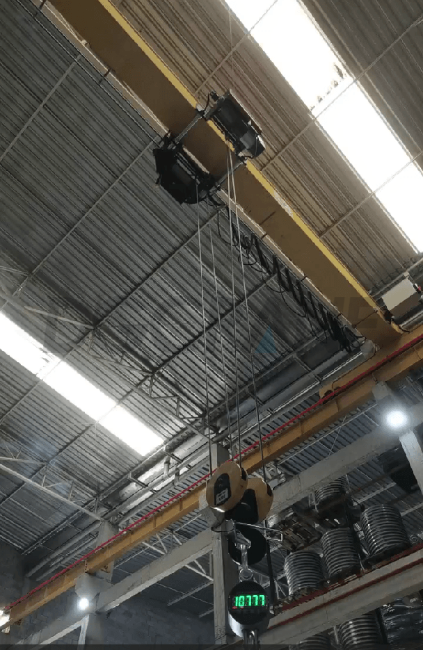
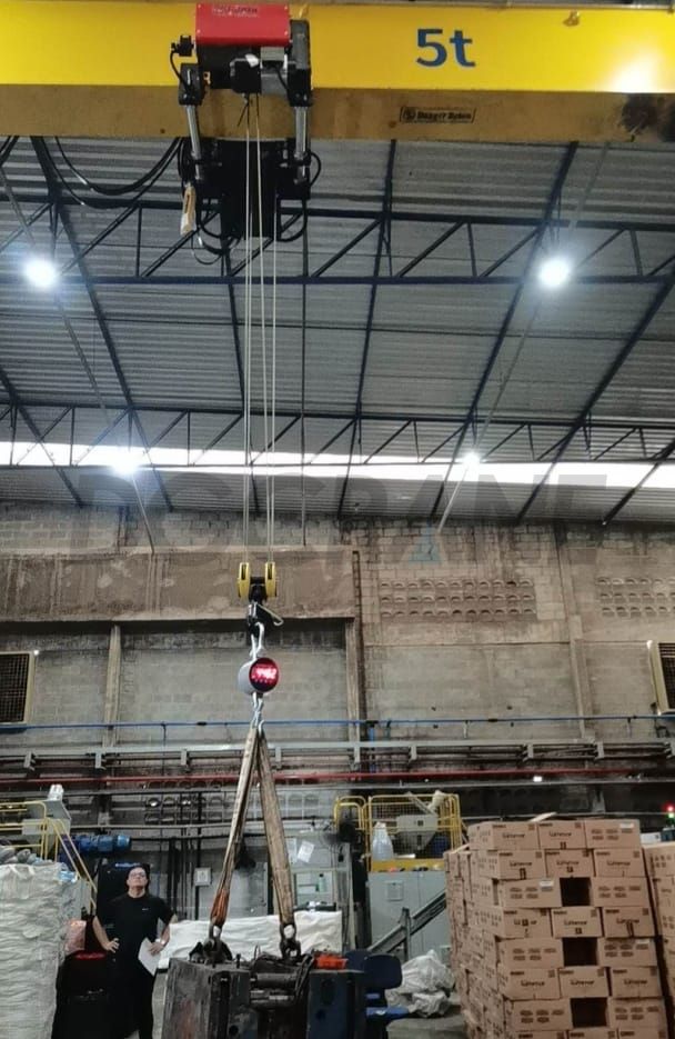
The load testing phase was the most critical day of the process. Engineers first conducted three no-load runs, confirming the absence of abnormal noise, vibration, or rail binding. Next, rated load tests were performed: the two HD single-girder overhead cranes lifted counterweights of 5t and 10t, respectively, executing lifting, lowering, and full-travel trolley and bridge movements at both high and low speeds. Finally, static load tests were conducted. The 5t and 10t HD single-girder overhead cranes suspended their respective loads 100 mm above the ground for 10 minutes, during which engineers measured and recorded the downward deflection at the mid-span of the main girders. Upon unloading, the girders returned to their original state with no residual deformation. Both the load tests and static load tests were passed on the first attempt.
From the initial inquiry in 2025—including the engineer’s first trip to Brazil for a site survey, the completion of production within 30 days, and the sea shipment and customs clearance—to the engineer’s second trip in 2026 to finalize installation and commissioning, the two HD single-girder overhead cranes are now operating reliably in the client’s injection molding workshop.
Get A Customized Solution
The client in this case was the manager of an injection molding plant with little knowledge of the crane industry. To be honest, most of our clients are not crane experts—and that is perfectly normal. You don't need to know the ins and outs of cranes; there is only one thing you need to know: what needs to be lifted in your workshop, and how heavy and high it is.
Leave the rest to us.
What DGCRANE can do:
- Tailored Operational Analysis: We provide customized lifting solutions based on your workshop layout, material types, handling frequency, and existing infrastructure. Every parameter—including span, lifting height, operating speed, power supply method, and control logic—is tailored to your specific needs. We also accommodate special operating conditions such as extreme temperatures, explosion-proof requirements, and cleanroom environments.
- Global On-Site Experience: Our engineers have frequently traveled to project sites worldwide to conduct surveys, supervise installation, and provide operational training. We have successfully delivered projects in regions including Brazil, Southeast Asia, the Middle East, and Africa.
- Comprehensive Documentation and Acceptance: Provision of load test reports, static load test reports, operation manuals (in multiple languages), and routine maintenance procedures, ensuring full traceability from the date of acceptance.
- Integrated Steel Structure Supply: Steel components—such as crane runway beams, rails, and conductor bar brackets—are designed, manufactured, and shipped together with the crane, eliminating the need to coordinate with separate suppliers for the crane and the steel structure.
Send us your workshop layout or lifting requirements, and DGCRANE's engineering team will provide a one-on-one customized solution and technical quotation within 24 hours.

Zora Zhao
Expert in Overhead Crane/Gantry Crane/Jib Crane/Crane Parts Solutions
With 10+ years of experience in the Crane Overseas Export Industry, helped 10,000+ customers with their pre-sales questions and concerns, if you have any related needs, please feel free to contact me!
WhatsApp: +86 189 3735 0200
Email: zorazhao@dgcrane.com
Contact Details
DGCRANE is committed to providing the professional Overhead crane products and relavent service. Exported to Over 100 Countries, 5000+ Customers Choose Us, Worth to be Trusted.
Get In Touch
Fill out your details and someone from our sales team will get back to you within 24 hours!
Subscribe to our newsletter
The latest DGCRANE price list, news, articles, and resources.
- Overhead Cranes
- Single Girder Overhead Cranes
- Double Girder Overhead Crane
- Low Headroom Overhead Cranes
- Underslung Cranes
- FEM Standard Overhead Cranes
- Grab Bucket Overhead Crane
- Manual Overhead Cranes
- LDP Single Girder Overhead Cranes with Side-Mounted Hoists: Optimal Solution for Low-Ceiling Workshops