


-
INDUSTRIES
-

Precast Concrete Plant
-

Steel Industry
-
Paper Industry
-
Waste to Energy and Biomass Industry
-
Power Industry
-

Overhead Cranes for Automotive Production: Smart Solutions for Enhanced Efficiency
-
Port Machines Industry
-

Manufacturing Industry
-
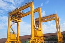
Different Types of Container Cranes, Shipyard Cranes, Cargo Cranes Used in Port, Harbor and Quay
-

Overhead Cranes for Timber Lifting: Efficient and Safe Wood Handling
-

Overhead Cranes for the Aviation Industry: Streamlining Aircraft Assembly, Maintenance, and Repair
-

Overhead Cranes for Food and Beverages: Ideal for improving productivity and food safety
-

Overhead Cranes for Aerospace Industry: Key Role in Efficient Rocket Manufacturing and Launch
-
-
EQUIPMENT
-
Overhead Cranes
-
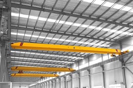
Single Girder Overhead Crane
-
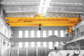
Double Girder Overhead Crane
-
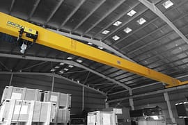
FEM Standard Overhead Cranes
-
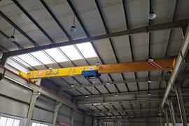
Low Headroom Overhead Cranes
-
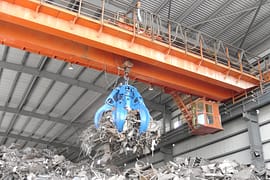
Grab Bucket Overhead Crane
-

Electromagnetic Overhead Cranes with Lifting Magnet
-
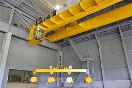
Electromagnetic Overhead Cranes with Magnet Beam
-
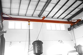
Manual Overhead Cranes
-
Double Trolley Overhead Cranes
-
LDP Single Girder Overhead Cranes
-
- Eot Cranes
- Gantry Cranes
- Jib Cranes
-
Hoist & Winch Trolley
-
Electric Wire Rope Hoists
-
FEM Standard Wire Rope Electric Hoists
-
FEM Standard Electric Chain Hoists
-
Crane Trolley
-
Chain Hoists
-
Electric Winch
-
Manual Chain Hoists
-
Double Girder Trolley Electric Hoists
-
Low Headroom Wire Rope Electric Hoist
-
Electric Hoist for Molten Metal
-
Pneumatic (Air) Chain Hoists
-

Lever Hoists
-
Electric Hoists
-
- Workstation Cranes
- Portable Gantry Cranes
- Explosion Proof Cranes & Hoists
- Special Cranes
- Port Cranes
- Electric Transfer Carts
-
Overhead Cranes
-
CRANE PARTS
- Crane Wheel Assembly
- Crane Grab Buckets
- Crane Tongs
- Crane Spreader
- Crane Drives
-
Crane Electrical Equipment
-
Overload Limiter
-
Crane Cabin
-
Crane Power Supply System
-

Explosion Proof Crane Radio Remote Controls
-

Joystick Type Crane Radio Remote Controls
-

Pushbutton Type Crane Wireless Remote Controls
-
Single-pole Insulated Conductor Rails
-
Enclosed Conductor Rails
-
Seamless Conductor Rails
-
Copperhead Conductor Rails
-
Overhead Crane Cables
-
- Other Cranes Parts
- ABOUT US
- CONTACT US






Overhead Crane Planetary Gearbox: How Four Components Create Multiple Ratios
Table of Contents
Take apart an automatic transmission, an overhead crane planetary gearbox, or certain robot joint reducers, and you will repeatedly see a very distinctive gear structure: a small gear in the center, several small gears around it, and an outer ring with internal teeth.
It looks like nothing more than “several gears arranged in a circle,” yet it can provide speed reduction, speed increase, reverse rotation, and coaxial transmission in a very small space. It can even produce a completely different planetary gear ratio simply by changing which component is fixed, which is the input, and which is the output.
This is a planetary gear set. What makes it powerful is not the number of gears, but the strict kinematic relationship among its four core components.
Remember one point first: a planetary gear set does not change its ratio by “switching to another set of gears.” Instead, it redistributes the motion of the entire gear set by changing the input, output, and fixed relationships among the sun gear, ring gear, and planet carrier.
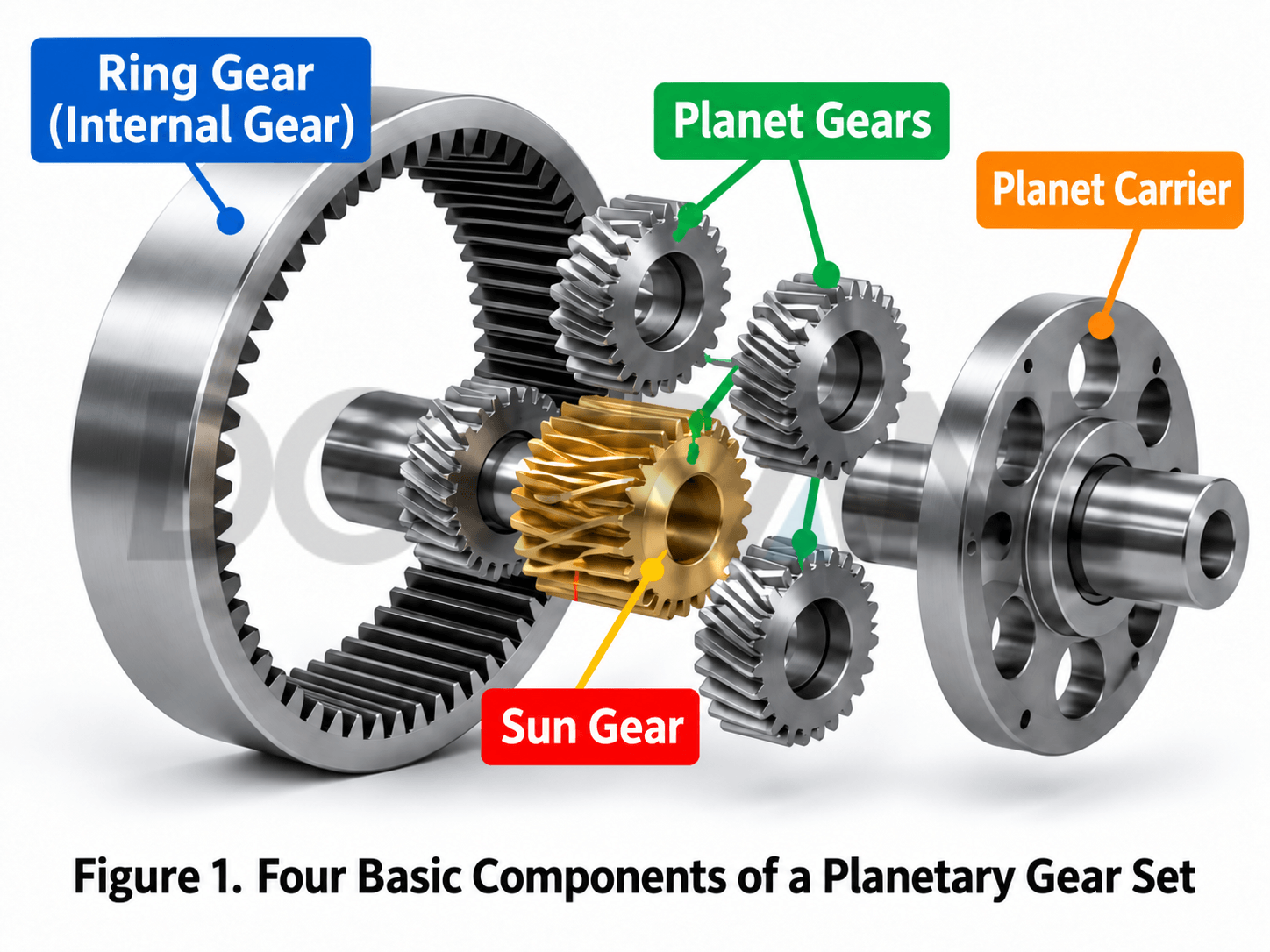
1. What Are the Four Components of a Planetary Gearbox?
1.1 Sun Gear: The Central Gear of the System
The sun gear is located at the center and normally meshes with several planet gears at the same time. In many reducers, the input shaft of an electric motor or hydraulic motor is connected directly to the sun gear, so it often carries the high-speed input. The number of teeth on the sun gear is denoted by Zs, and its angular speed by ωs.
1.2 Planet Gears: Rotating on Their Own Axes While Orbiting the Sun
The planet gears are the most interesting part of the mechanism. Each planet gear rotates around its own axis while revolving around the sun gear with the planet carrier. At the same time, it meshes with both the sun gear and the internal ring gear.
Increasing the number of planet gears does not change the theoretical ratio of a simple planetary gear mechanism. However, when the design is appropriate and load sharing is good, multiple planet gears can share the load. This is one reason a planetary gearbox can achieve high torque density.
1.3 Ring Gear: Enclosing the Entire Gear Set
The ring gear is located on the outside, with its teeth facing inward. It forms an internal mesh with the planet gears. The ring gear can be fixed or used as either the input or output element. The number of teeth on the ring gear is denoted by Zr, and its angular speed by ωr.
1.4 Planet Carrier: Determining How the Planets Move as a Group
The planet gears do not rotate unsupported. Their shafts are mounted on the planet carrier. The carrier connects the planet gears into one assembly, so rotation of the carrier represents the revolution of the planet gears around the sun gear. The angular speed of the carrier is denoted by ωc. In many industrial reducers, a common arrangement is to fix the ring gear, use the sun gear as the input, and use the planet carrier as the output.
| Component | Common symbol | Main function | Typical state |
|---|---|---|---|
| Sun gear | Zs/ωs | Central gear that transmits motion and torque to the planet gears | Often used as the high-speed input |
| Planet gears | Zp/ωp | Mesh with both the sun gear and ring gear | Rotation plus revolution |
| Ring gear | Zr/ωr | Outer internal gear that constrains and participates in transmission | Can be fixed, input, or output |
| Planet carrier | ωc | Supports the planet gear shafts and produces orbital motion | Often used as the low-speed output |
2. The Real Core of the Planetary Gear Ratio: One Equation Links the Three Rotating Members
In an ordinary fixed-axis gear train, the positions of the two gear axes are fixed, so the ratio is relatively intuitive. A planetary gear set is different: the axes of the planet gears move with the planet carrier, so the simple rule of “driving-gear teeth divided by driven-gear teeth” cannot be applied directly.
For the most common simple planetary gear set, the Willis equation expresses the speed relationship among the sun gear, ring gear, and planet carrier:
Here, ωₛ, ωᵣ, and ω꜀ are the angular speeds of the sun gear, ring gear, and planet carrier, respectively; Zₛ and Zᵣ are the numbers of teeth on the sun gear and ring gear.
The most important part of this equation is not the minus sign, but the fact that ω꜀ is subtracted from both speeds. In other words, the meshing relationship in a planetary gear set must be understood in a reference frame that rotates together with the planet carrier.
Once the speed or fixed condition of any two members is known, the speed of the third can be calculated. The same gear set can therefore produce completely different motion results without changing the tooth counts.
Why does this seem so ingenious? Among the sun gear, ring gear, and planet carrier, fixing any one member and choosing the input and output from the other two produces different combinations of reduction, speed increase, or reverse rotation. The structure remains unchanged, but the motion relationship changes.
3. The Most Common Arrangement: Ring Gear Fixed, Sun Input, Carrier Output
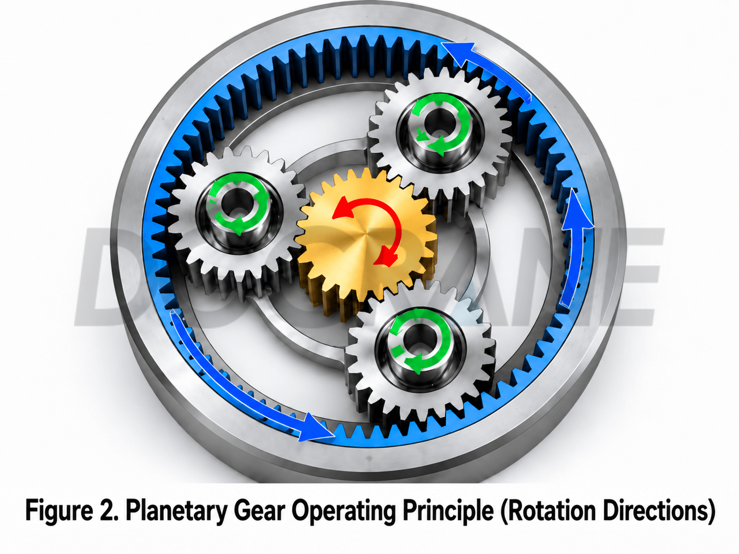
This is a common basic arrangement in overhead crane travel gearboxes, slewing reducers, and many industrial planetary gearboxes. Let the ring gear be fixed, so ωᵣ = 0. Substituting this condition into the Willis equation gives:
If the sun gear has 20 teeth and the ring gear has 60 teeth:
The sun gear turns four revolutions while the planet carrier turns approximately one revolution. If the sun gear input speed is 1,200 r/min, then, ignoring losses, the theoretical output speed of the planet carrier is approximately 300 r/min.
This is typical speed reduction with torque multiplication. In theory, when losses are ignored, reducing the speed to approximately one quarter increases the output torque accordingly. Actual equipment must also account for gear-meshing losses, bearing losses, lubrication conditions, and other factors.
4. The Same Gears Produce Completely Different Results When a Different Member Is Fixed
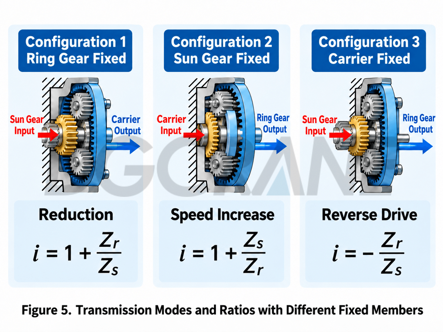
| Fixed member | Input | Output | Typical result | Characteristic |
|---|---|---|---|---|
| Ring gear | Sun gear | Planet carrier | Reduction, same direction | The most common planetary reduction arrangement |
| Sun gear | Ring gear | Planet carrier | Reduction, same direction | A milder ratio |
| Planet carrier | Sun gear | Ring gear | Reverse rotation | Forms fixed-axis reverse transmission |
| None; two members are controlled | Depends on control method | Third member | Variable ratio | Basis of automatic transmission and power-split systems |
A common misunderstanding is that a planetary gear set naturally has only one ratio. The ratio is determined not only by the tooth counts, but also by which member is fixed, which is the input, and which is the output.
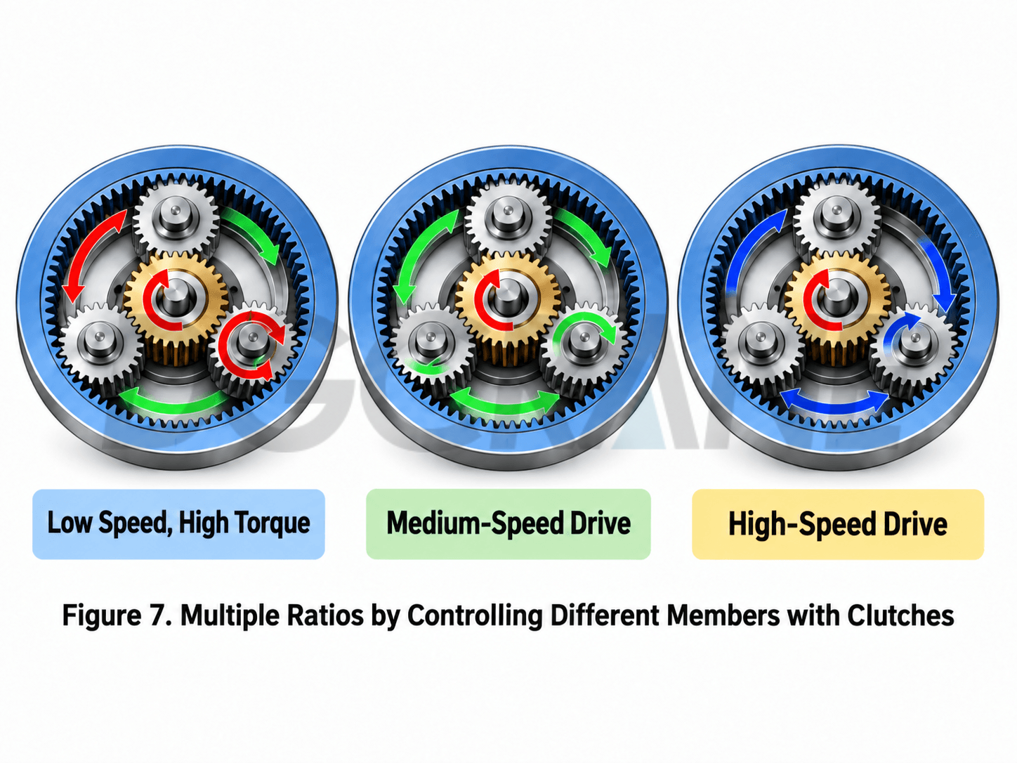
If all three main members are allowed to move, and one member is controlled by a clutch, brake, or another power source, the system can provide more complex multi-speed transmission or power-split functions. This is an important reason planetary gear sets are widely used in automatic transmissions and hybrid power-split mechanisms.
5. Why Can a Planetary Gear Set Transmit High Torque in Such a Small Space?
The reason is not mysterious. The key is “multiple simultaneous mesh points plus coaxial arrangement.”
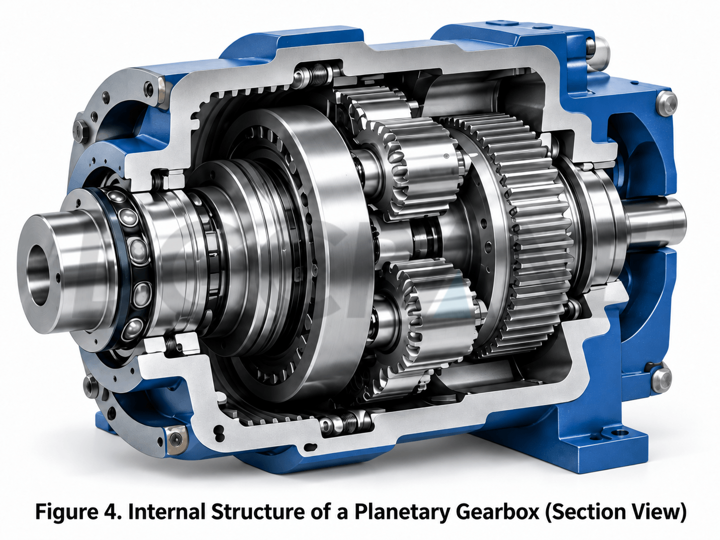
In an ordinary gear pair, the main load is concentrated on one meshing pair. In a planetary mechanism, several planet gears can mesh with the sun gear and ring gear at the same time. When the design is appropriate and load distribution is uniform, the input torque can be shared by multiple planet gears.
At the same time, the sun gear, ring gear, and planet carrier can be arranged on the same axis. The input and output shafts do not need to be laterally offset as they are in an ordinary parallel-shaft reducer. The result is higher torque density and a more compact arrangement within a similar overall size.
However, “more planet gears” should not be understood too simply.
Increasing the number of planet gears does not change the theoretical ratio, but this does not mean the load will automatically be distributed equally. Manufacturing errors, lead errors, bearing clearance, planet-pin positioning accuracy, and structural deformation all affect load sharing. High-load planetary gearboxes often require dedicated load-sharing design.
6. Why Are Planetary Gears Particularly Popular in Automatic Transmissions?
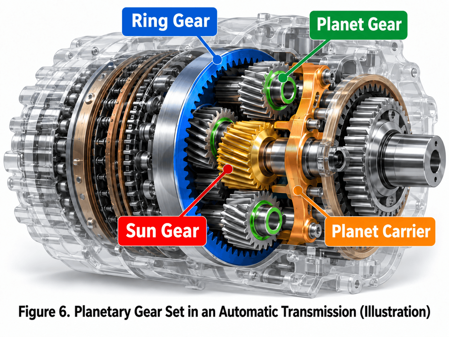
A planetary gear set has an advantage that is difficult for an ordinary fixed-axis gear train to provide at the same time: clutches and brakes can control the connection and locking of different members, allowing the same gear set to produce multiple ratios.
As a conceptual example, one gear position may fix the ring gear, use the sun gear as the input, and use the planet carrier as the output. Another gear position changes the locked member. A clutch can also lock two members together to produce a direct-drive state close to 1:1.
This means the transmission does not need a completely separate fixed-axis gear pair for every gear position. Its structure can be more compact, and its shifting logic can be more flexible.
It should be emphasized that modern automatic transmissions normally use compound planetary gear sets, multiple planetary rows, and combinations of several clutches. Their actual ratio calculations are far more complex than those of a single simple planetary gear set.
7. Why Do Overhead Cranes and Construction Machinery Rely on Planetary Reducers?
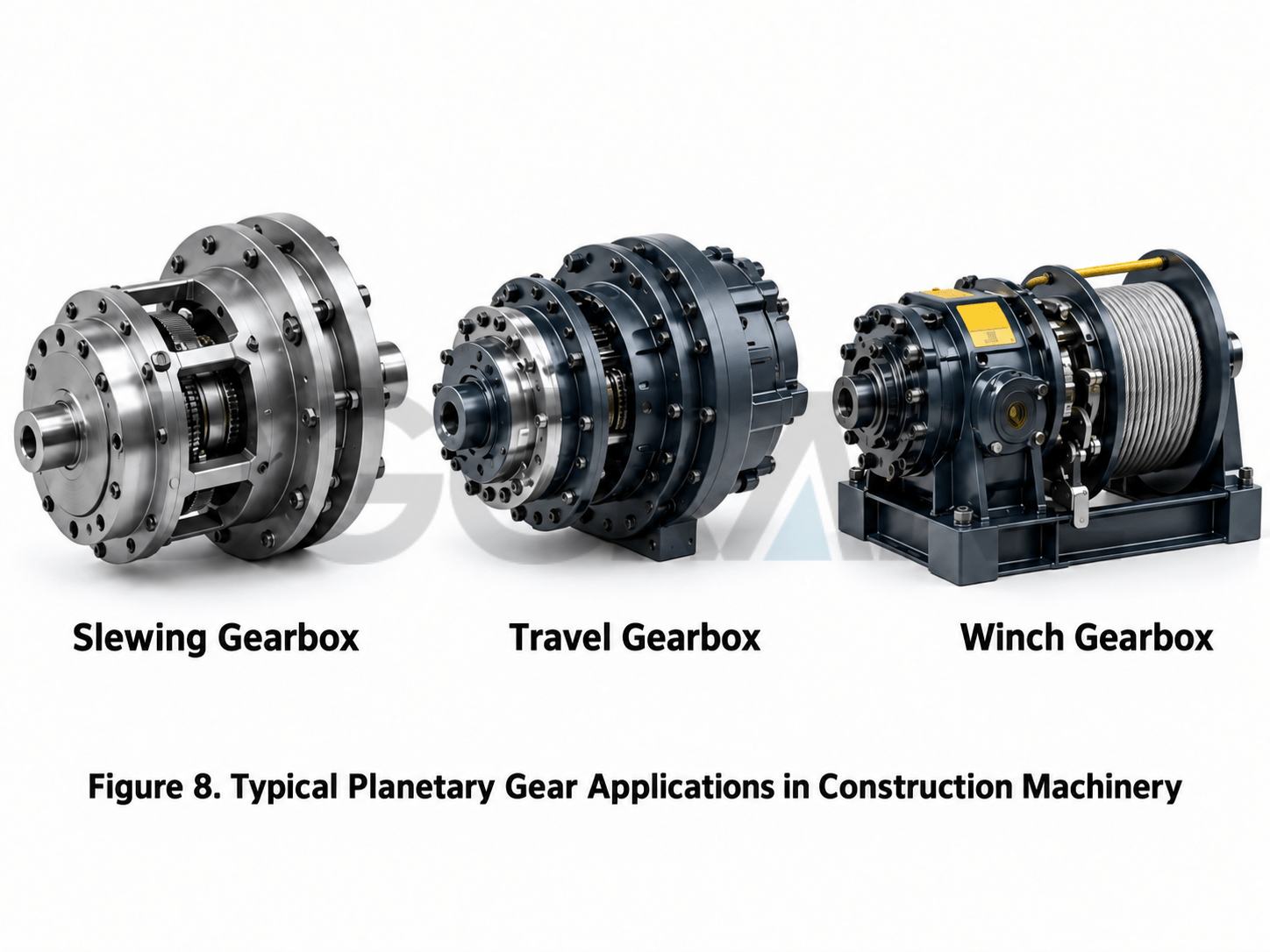
Planetary gears can be found in excavator travel motors, overhead crane travel mechanisms, certain slewing mechanisms, overhead crane winch gearboxes, and large industrial drives.
Overhead cranes and construction machinery must resolve a typical conflict: the hydraulic motor or electric motor runs at relatively high speed, while the drive wheel, rope drum, or slewing mechanism requires low speed and high torque. At the same time, installation space is often very limited.
A planetary reducer is well suited to these operating conditions: it is coaxial and compact, can provide a large reduction ratio, and can use multiple stages in series to further reduce speed and increase output torque.
However, a planetary gear set is not a universal solution that works merely by being installed. Actual design must also check tooth-surface contact strength, tooth-root bending strength, bearing life, planet-pin loading, lubrication, thermal balance, efficiency, impact load, and braking requirements.
8. An Easily Overlooked Geometric Condition: Tooth Counts Cannot Be Chosen Arbitrarily
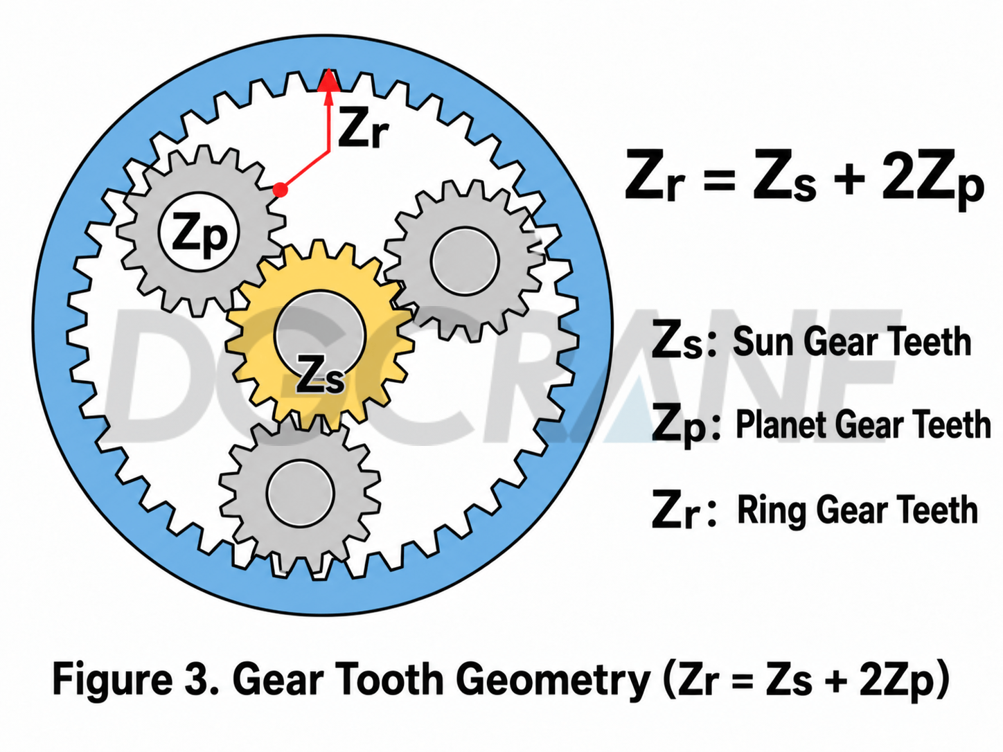
In a simple planetary gear set, the sun gear, planet gears, and ring gear must satisfy a basic geometric relationship. For a simple arrangement with the same module and standard meshing, the common relationship is:
If the sun gear has 20 teeth and the planet gear has 20 teeth, the ring gear normally needs 60 teeth to satisfy the center-distance relationship.
If multiple planet gears are to be evenly arranged, the assembly phase and possible geometric interference between adjacent planet gears must also be checked. In other words, calculating a ratio is only the first step. Further design is required to make the gear set manufacturable, assemblable, and capable of carrying the load.
9. Four Statements Are Enough to Understand a Planetary Gear Set
- The sun gear is at the center; the planet gears rotate on their own axes and revolve around the sun; the ring gear surrounds them; and the planet carrier carries the planet gears around as a group.
- The number of planet gears generally does not change the theoretical ratio, but the gears can share the load when load distribution is properly designed.
- The same planetary gear set can produce different reduction, speed-increase, or reverse relationships by changing the fixed member, input member, and output member.
- The most common reduction arrangement fixes the ring gear, uses the sun gear as the input, and uses the planet carrier as the output. In this case, i = 1 + Zᵣ / Zₛ.
Final Note: Its Real Strength Is Not the Number of Gears, but the Use of Degrees of Freedom
An ordinary gear drive is more like two people holding hands: one turns, and the other follows, so the relationship is direct. A planetary gear set is more like a group of people moving together on a rotating platform. The platform itself can move, and the outer ring can also move, so the same gear combination can produce completely different results.
This is the most fascinating feature of a planetary gear set. With four core components—the sun gear, planet gears, ring gear, and planet carrier—it combines compact structure, multiple ratios, coaxial transmission, and high torque density in a single mechanism.
The next time you see a planetary reducer on construction machinery, ask three questions first: Which member is fixed? Which member is the input? Which member is the output? Once these three questions are answered, you can basically understand why the planetary gear set rotates as it does.
Note: This article is intended as an introduction to mechanical principles. The equations are based on the kinematic relationships of an ideal simple planetary gear set. Actual overhead crane gearbox design must also account for tooth-profile modification, manufacturing accuracy, load sharing, strength, efficiency, lubrication, bearings, and thermal balance.

Zora Zhao
Expert in Overhead Crane/Gantry Crane/Jib Crane/Crane Parts Solutions
With 10+ years of experience in the Crane Overseas Export Industry, helped 10,000+ customers with their pre-sales questions and concerns, if you have any related needs, please feel free to contact me!
WhatsApp: +86 189 3735 0200
Email: zorazhao@dgcrane.com
Contact Details
DGCRANE is committed to providing the professional Overhead crane products and relavent service. Exported to Over 100 Countries, 5000+ Customers Choose Us, Worth to be Trusted.
Get In Touch
Fill out your details and someone from our sales team will get back to you within 24 hours!
Subscribe to our newsletter
The latest DGCRANE price list, news, articles, and resources.
- Overhead Cranes
- Single Girder Overhead Cranes
- Double Girder Overhead Crane
- Low Headroom Overhead Cranes
- Underslung Cranes
- FEM Standard Overhead Cranes
- Grab Bucket Overhead Crane
- Manual Overhead Cranes
- LDP Single Girder Overhead Cranes with Side-Mounted Hoists: Optimal Solution for Low-Ceiling Workshops