


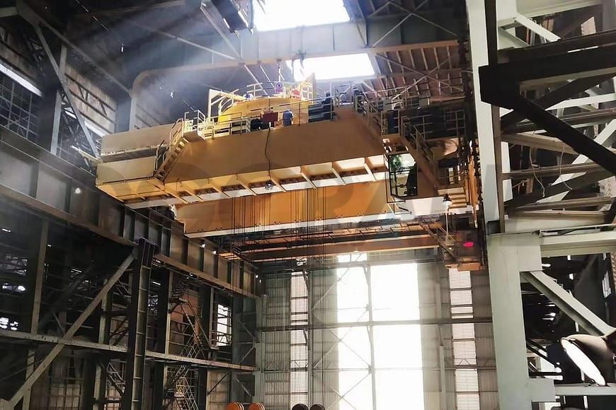
Automatic Rotary Feeding Overhead Crane: 330° Rotation & High Precision Positioning for Steelmaking
The advent of the automatic rotary feeding overhead crane has solved the problems of limited space in production workshops, large tilting angles of material troughs, and high feeding tonnage. The upper trolley innovatively adopts a rotating mechanism to realize the automatic rotation of the material trough. Moreover, the application of the four-point double-linked gantry hook beam group has improved the inherent safety of the crane. It has the characteristics of strong operability, high safety factor, high stability, and low friction. It is widely used in the steel industry and has become a representative of the new generation of special cranes in the converter steelmaking process.
- Capacity: 35t + 35t
- Upper trolley rotation angle: 330°
- Chute tilt angle: 75°
- Distance between hook beams in the same group: 2,110mm
- Distance between hook beams in front and rear groups: 3,500mm


Operating Principle of Automatic Rotary Feeding Overhead Crane
The trolley traveling mechanism can travel along the bridge frame and also drive the lifting mechanism to rotate when the trolley rotates, thereby adjusting the position of the material trough discharge port so that the orientation of the material trough discharge port is opposite to that of the boiler furnace opening. This allows the material through the discharge port and the boiler furnace opening to cooperate in discharging materials. Through the cooperation of the trolley traveling mechanism and the crane traveling mechanism, the material trough can move in the X and Y directions while also rotating, allowing the material troughs to be placed sequentially in the plant, thus making reasonable use of the plant space.
Features of Automatic Rotary Feeding Overhead Crane
- An additional trolley rotation mechanism has been added, enabling the trolley to rotate 330° with controllable starting and braking.
- Flexible and accurate adjustment of the feed trough angle.
- The dedicated gantry crane features four hooks that distribute force evenly, eliminating the need for manual assistance from ground operators. It can automatically lift the scrap steel feed trough, doubling the efficiency.
- Increased load capacity eliminates the risk of breakage in the auxiliary lifting hooks, laying a solid foundation for increasing the amount of scrap steel added to the converter. At least 5 tons of additional scrap steel can be added per furnace.
- Significantly reduced maintenance and labor costs.
Problems Solved by Automatic Rotary Feeding Overhead Crane
- The hopper is close to the wall, limiting the operating space for the hook.
- The operator’s cab is adjacent to a ladle engulfed in flames, requiring a high fire resistance and heat resistance rating for the structure.
- To dump all waste material in one go, the hopper angle must be greater than 60°.
- Cold material hoppers can only be hoisted using four steel cables, requiring manual assistance for hooking and unhooking.
- The trolley cannot rotate; the incoming material hopper must be manually pushed to rotate 90°.
- The hook lacks a braking system; it is difficult to stop manually after pushing the hopper, requiring manual braking.
- In confined spaces, operators are highly susceptible to injury from being crushed by adjacent material hoppers, posing a significant safety hazard.
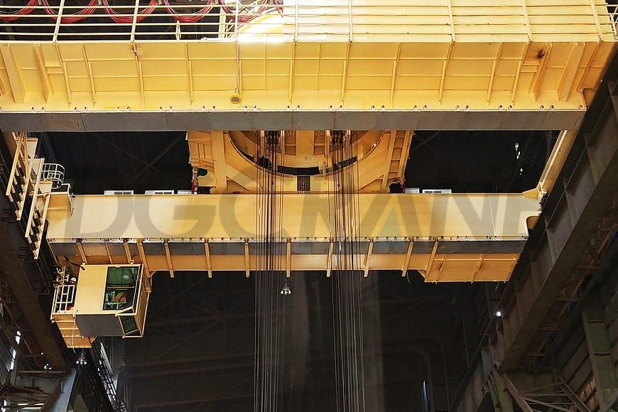
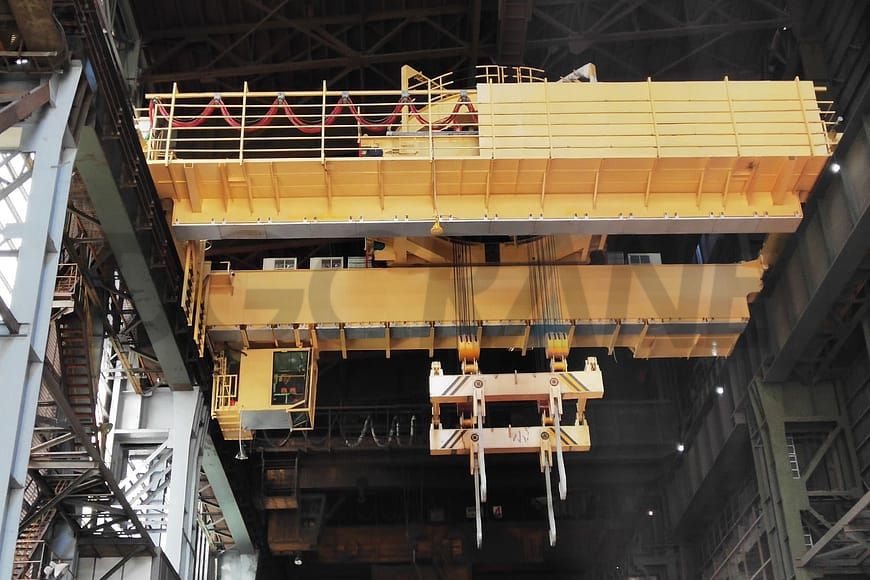
Special Components of Automatic Rotary Feeding Overhead Crane
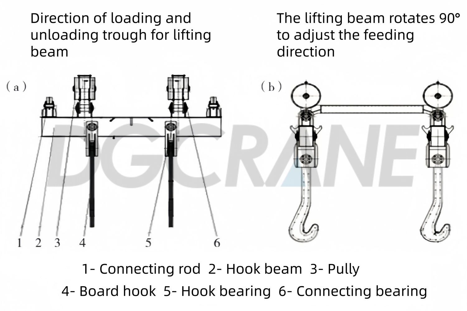
Four-point Twin Fixed Gantry Hook Beam
This specialized lifting device, used for the horizontal lifting and tilting of scrap steel troughs, consists of two sets of gantry hook beams (front and rear), four sets of pulley blocks, four plate hooks, and two sets of interference-prevention connecting rods. The center distance between the two sets of hook beams is 3500mm, and the center distance between the two plate hooks on the same hook beam is 2110mm. The four plate hooks can be directly hooked onto the four trunnions of the trough, facilitating crane operator operation and enabling horizontal lifting of the trough.
Simultaneously, the independently operable hook beams are connected, and the pulley blocks and hook beams, as well as the hook beams and plate hooks, are designed with hinged shaft structures, allowing for flexible rotation and achieving the requirement of non-interference during trough tilting. The pulley blocks on the two sets of hook beams are connected to the four drums of the lifting mechanism. The two independently operable lifting mechanisms can drive the two sets of hook beams to operate separately or simultaneously.
Lifting Mechanism
The hoisting mechanism consists of two independent sets of mechanisms to control the independent movement of the front and rear gantry hook beams and adjust the height difference. When the material trough is being moved horizontally, the main hoisting (front) gantry hook beam is raised to maintain a front-high, rear-low position, preventing cold material from spilling out of the trough.
When adding cold material into the converter, the auxiliary hoisting (rear) gantry hook beam is raised upwards, tilting the trough towards the opening and allowing the scrap steel to slide into the converter furnace.
Rotary Mechanism
It mainly consists of a motor, a reducer, rotating wheels, guide wheels, and a circular track. The rotating wheels consist of one set of driving wheels and two sets of driven wheels, evenly distributed at 120° intervals around the circumference. Three guide wheels are located inside the circular track, also evenly divided at 120° intervals around the circumference. The rotating motor drives the driving wheels to rotate freely on the circular track. To prevent the trolley cable from being twisted, the limit angle and the buffer base are set at a 30° angle, allowing the upper trolley to rotate at a 330° angle.
Simultaneously, the rotation of the trolley drives the lifting mechanism on the upper trolley to rotate, which in turn causes the material trough being lifted by the lifting mechanism to rotate automatically, solving the safety hazards associated with manual operation. The upper trolley is mounted on the lower trolley, which drives it in a reciprocating linear motion.
Trolley Traveling Mechanism
The lower trolley’s transmission system is driven by two separate drive systems. Each drive system consists of a motor, a reducer, a drive wheel set, and a driven wheel set. The wheels move linearly on the main beam track. The lower trolley drives the upper trolley and the material trough to move in both directions, facilitating the alignment of the cold material trough with the converter opening.
Crane Traveling Mechanism
Located primarily at the four corners of the main girder bridge, each transmission system is independent, totaling four systems. Each transmission system consists of a motor, reducer, travelling drive wheel set, driven wheel set, and coupling. The travelling transmission system drives the entire vehicle to move laterally on the factory rails.


